T.Yoshida, O.Nozaki, A.Ogawa, Y.Ro+, T.Nishizawa,
K.Kikuchi, F.Zhou, Y.Fujisawa, M.Matsushita
Virtual Turbine Team, High Temperature Materials 21 Project
National Aerospace Laboratory, Chofu, Tokyo 182-8522, Japan
+ National Research Institute for Metals, Tsukuba, Ibaraki 305-0047, Japan
Development of advanced high-temperature materials is conducted in the project for those applications to high-temperature machinery such as a gas turbine. It is very important to evaluate the developed material under its practical use condition, whereas manufacturing a practical model should come after various fundamental surveys of characteristics of the material itself. Hence development of a virtual gas turbine (VT) has been included in the project. This is to be used not only among researchers engaged in the project, but also by worldwide visitors to "HTM21 home page". For the latter users, a virtual gas turbine will be a type of a simplified one.
A complete system of a virtual gas turbine is to be built under collaboration with the Toshiba Corporation and the virtual turbine team engages in development of advanced gas turbine technology. The outputs from the team are to be introduced to a design procedure of the VT. The technology provides three-dimensional information on heat transfer, fluid flow, strength and material properties in the region of the first stage turbine vanes and blades.
At present, a medium scale gas turbine of 17MW class output power is adopted as the first virtual gas turbine. Construction of one-dimensional virtual gas turbine is now under way in which representative performances of the individual components, such as compressor, combustor and turbine are given and global performances such as thermal efficiency, output power and life are obtained. This model is named as VT-M10. The work will eventually be extended to three-dimensional model with which one can discuss characteristics of turbine vanes and blades in detail.
In parallel with this work, the virtual turbine team has performed fundamental preparations for advancement of the above VT-M10. Those activities are summarized in the successive sections.
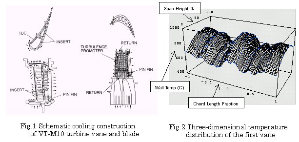
Advanced gas turbine engines mostly introduce elaborate cooling construction in hot parts such as high-pressure turbine stages. Figure 1 shows schematic cooling constructions of the first stage turbine vane (left) and blade (right) of VT-M10. These are considered typical applications of all type of the cooling constructions. They include film cooling, impingement cooling, pin fine cooling and effective forced convection cooling by turbulence promoters in serpentine cooling passages.
As the first step of the present work, formulation of average wall temperature characteristics with respect to cooling air flow rate was completed for all the high-pressure turbine stages. Those are the vanes and blades in the first and second stages. The formulation is made in dimensionless form, that is, the relation between cooling effectiveness versus cooling air flow rate ratio and will be applied in the one-dimensional virtual gas turbine model. Subsequently, an extension to the three-dimensional form of the relation has been made. Figure 2 shows a representative result for the first stage turbine vane. With this kind of formulation, one can figure out local wall temperature and discuss validity of the material planned for the application.
The main part of this work hereafter is to give three-dimensional database of heat transfer and pressure loss characteristics around and inside the turbine airfoils for further advanced virtual gas turbines. Those will be conducted successively in collaboration with the work for the virtual turbine construction.
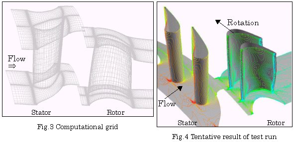
To provide the prototype virtual gas turbine with information about aerodynamics, the study of numerical simulation of turbine aerodynamics with film-cooling has been initiated. In the FY1999 we fixed the configuration of the model VT-M10, generated a computational grid, and conducted a test run of flow calculation with adiabatic boundary conditions on the walls. The computational grid and a sample of flow fields obtained through the flow calculation are shown in Figures 3 and 4, respectively. In Figure 4, static pressure contours are shown with color variation for three pitches of passages. Unsteadiness of the flow is not taken into account at present. Flow calculation was therefore conducted for only one pitch of each cascade, and the boundary conditions are given on the contact plane between two cascades using circumferential average of all flow variables.
In the next phase, we will conduct flow calculations in actual operating conditions and confirm the validity of the computer code by comparing with experimental data. Furthermore, we are planning to construct aerodynamic databases which give us information such as correlations between inlet angles and total pressure losses. It is also investigated how to incorporate the effect of cooling-air ejection in the calculation, though meaningful output has not been available so far. It is expected that databases will be obtained concerning cooling-air and heat-transfer in the future.
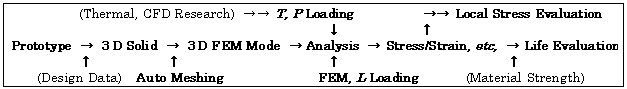
The structural analysis research in the team will be constituted by the following 4 steps: (1) Referring to the prototypes of turbine rotor or vane, 3-dimensional geometrical models of the parts will be formed; (2) Referring to the practical or designed operation condition, the load/constraint conditions, such as temperature (T) and air-pressure (P) distribution on the structural parts surface, will be determined; (3) Under specified operation conditions (centrifugal L, thermal T and/or aerodynamic P loading), the displacement, stress and strain, etc. will be calculated via structural FEM analysis; and finally (4) Fatigue and creep life of the turbine parts will be evaluated by applying the above calculated results, together with basic material data, to the available fatigue/creep theories and criterions.
The flowchart shown below illustrates the modeling process of turbine-rotor. Because the structure of a real turbine-rotor is much complicated, several simplified models are constituted to obtain guideline information. These models are: A simplified, solid turbine-rotor model (including rotor root); a blade model including blade-root fillet; and a hollow blade model with internal cooling passages. Structural analysis will be performed for these models to obtain whole field (macroscopic) stress distribution.
Local (concentrated) stress levels around the cooling air holes may later be estimated by microscopic analytical models with far field stress as the known value. In doing these jobs, the arrangement of calculation time and accuracy to the optimum balance is very important. The input quantities of T and P distributions on the turbine blade will come from the results of cooling performance research and CFD research in the team. In order to determine the adequate boundary conditions, comparison of the available experimental data is also important. Based on the results of displacement/ strain/stress distribution from structural analysis, the deformation of turbine blade, its creep life, fatigue life (HCF or LCF), etc., will be estimated by applying data of the developed high-temperature alloys, TMS-75, TMS-82, and so on. These material data would be obtained by independent material strength tests (Larson-Miller life tests, fatigue life tests, etc.), performed at NRIM and other institutes.
Fig.5 FEM model of solid turbine-rotor
As the start point, existing superalloy Mar-M247 (conventional casting, CC, [6]) is chosen as the model material for the structural analysis of virtual turbine blade. The mechanical responses of three simplified models, i.e., simplified solid turbine-rotor, solid turbine-blade, and hollow turbine-blade, were simulated when rating rotation speed were applied. Figure 5 shows the shape of the turbine rotor being analyzed. The turbine blade made by new high temperature materials, typically single crystal (SC) superalloy TMS-75 and TMS-82, will be simulated later, when sufficient mechanical data of these materials become available.
[1] Hijikata,T., Okamura,T., Fukuda,M., Ito,S., Cooling Characteristics of Turbine Airfoils from High-temperature Gas Turbine Full-scale Demonstrator Tests, Proc. of the Gas Turbine Lecture Meeting, Sendai, pp.185-192 (1990), [in Japanese]
[2] Gas Turbine Society of Japan, Cooling Technology for High-temperature Gas Turbines, Technical Committee Report (1997), [in Japanese]
[3] Nozaki, O., Kikuchi, K., Nishizawa, T., Kodama, H., Hashimoto, K and Shimizu, K., Research of CFD Application in HYPR Program, Proceedings of 3rd International Symposium on Japanese National Project for Super/Hypersonic Transport Propulsion System, pp. 185-190 (1999)
[4] Nozaki, O., Kikuchi, K., Nishizawa, T., Matsuo, Y., Ohba, Y and Kodama, H., Unsteady Three-Dimensional Viscous Flow Computations of Multiple-Blade-Row Interactions, ISABE Paper 99-7032 (1999)
[5] Yamawaki, S., Ohkita, Y., Kodama, H., Yoshida, T. Nozaki, O and Yamane, T., CFD Contribution to Development of HYPR Engine, AIAA Paper 99-0886 (1999)
[6] Aerospace Structural Metals Handbook, Code 4218, Mar-M247 (Dec., 1984)